MrCNC - part 2
Continued from part one...
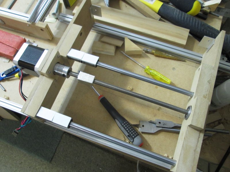
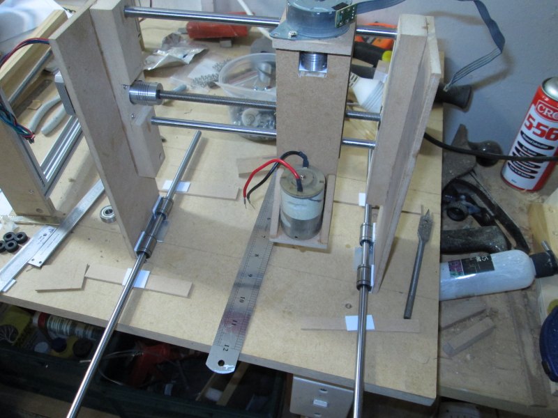
With the Z axis mostly done, it was time to turn my attention to the Y axis. The Y axis moves across the work, and supports the Z axis.
I started by cutting the two end pieces out and match-drilling them. I now had a problem though; my linear rails were each 1m long, and not especially cheap, so in order to gain some vertical work-height, I had reduced the Y length and now had a gap to span between the outside faces of the machine and the ends of the Y axis rails. In other words, I had to make some spacers. I made these out of 18mm MDF which gave me some extra space for the shaft coupler and 8mm ball bearing at the other end.
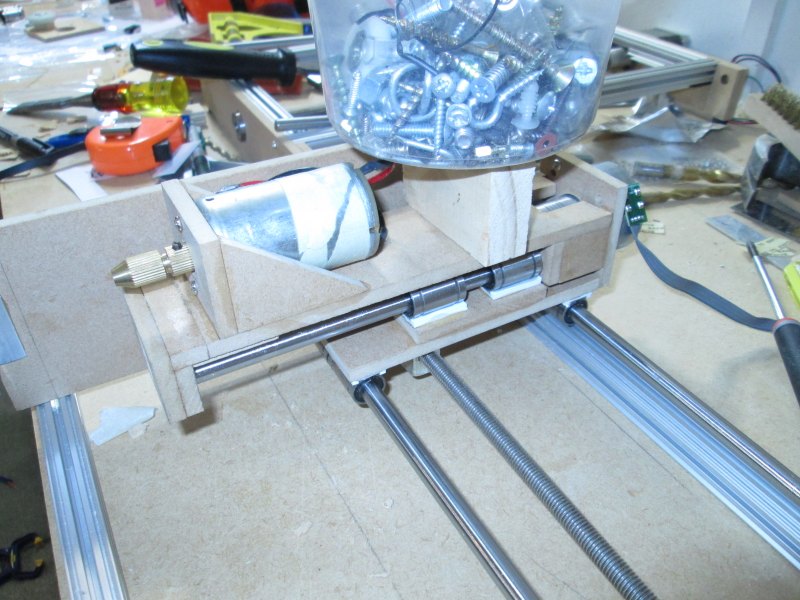
As per the Z axis I added the linear bearings with my patent-pending mounting blocks, and another cast "bolt". Some careful measurements and adjustments with my square ensured that both sides of the Y axis were true and then it was time to attach Z to Y. Copious amounts of 5 minute epoxy later:
Here it is with the motor and chuck in position. I realised I had made the Z axis around the wrong way but that was fairly easily solved with some quick re-gluing.
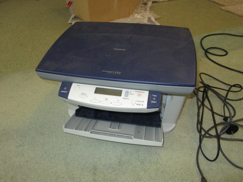
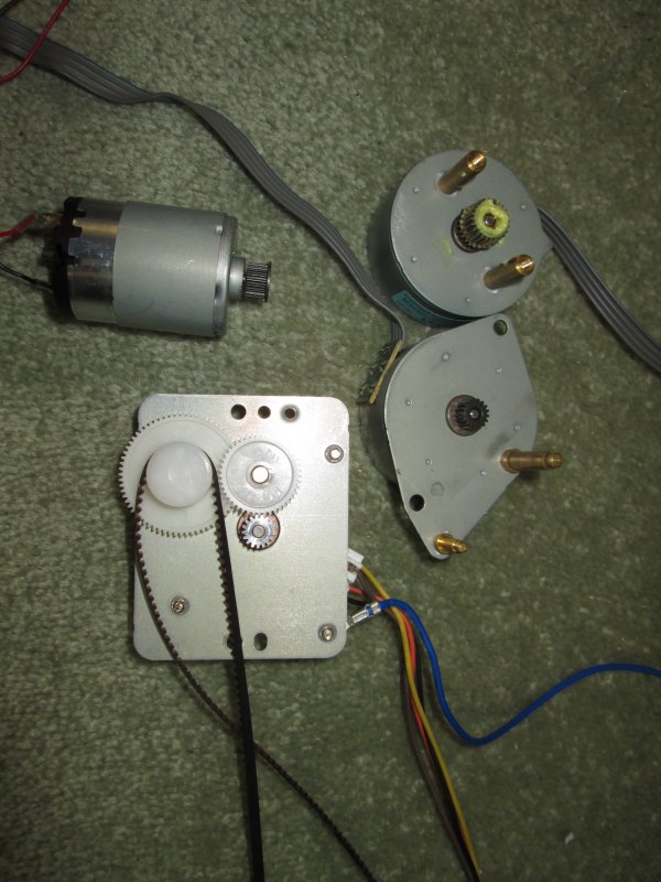
As an aside, the stepper motor for the Z axis is a nice wee one out of a printer/scanner/copier that I picked up for a couple of dollars at a garage sale.
I was rather pleased with it's contents:
3 stepper motors, one of them nicely geared with a very accurate timing belt, one DC motor with 2.3mm shaft, and 3 linear rails of various sizes. That and a beefy 4A DC power supply for $4! After verifying that I could get the remnants recycled, I went back a couple of weeks later to buy some more dead printers, only to find their entire stockpile was gone! I was not very impressed at all :-( New stepper motors cost $25+ each, so to get them for $1 each was very good value. Oh well...
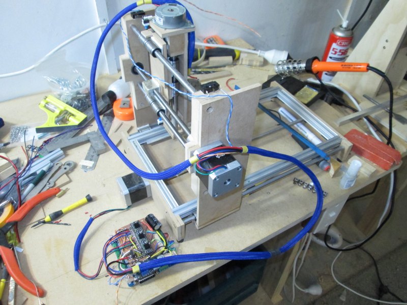
It was now time to connect the Y to the X axis. This was a bit tricky and required some careful gluing to ensure that the bottom linear bearings were all parallel. I did this by sliding the bearings onto the rails, then raising both sets of rails the exact same distance off my bench. (When I built my bench I went to considerable lengths to ensure it was flat and square, for reasons just like this).
Even though it's 5 minute glue, I left it to set up overnight to set up good and strong. To my great relief, the X axis bearings were very square and parallel, no binding going on here!
Now that X, Y, and Z were all assembled, it was time to wire things up. This proved to be the trickiest part of the whole operation.
It took several nights to wire up the motors and rest of the circuitry. To power the machine I had an old desktop PC that I'd brought up from Christchurch as carry-on luggage on an ATR72. No one at AirNZ seemed at all surprised when I turned up with it!
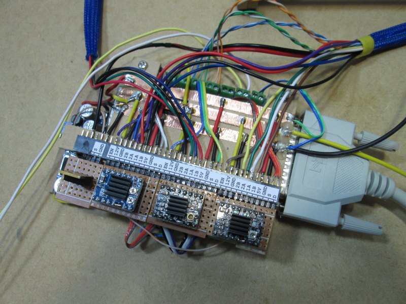
To connect the PC to the CNC machine, I had a small parallel port interface card from China. The quality of the PC was very good, with clear labels and little screw terminals to connect each function. I then built a "mother board" to hold my stepper motor driver boards, the power supplies, and mate with all the wires from the machine. To keep all the wires neat I used some nylon cable wrap from an old PC power supply.
Finally it was ready for testing, so I fired up the old PC and installed LinuxCNC on it. Unfortunately I quickly ran into all manner of problems. Both X and Y axis worked briefly, then stopped. X never moved again. Y would only jerk around occasionally. Z was erratic and would randomly go forward or back, different amounts each time. And the spindle didn't work at all!
After debugging it for a while I dismantled the whole thing and tested each channel in turn.
X axis has a blown stepper driver. Y axis had a half blown stepper driver. The Z axis motor (from the printer) had very weird wiring which took a few goes to get correct.
In the end I built up a tester circuit on my bench and tested each axis in turn. I soon discovered that the stepper drivers I'd been using were just plain troublesome. They were from Reprap.me in the Netherlands, via ebay, and I discovered a host of problems with them. First they were similar to what they were labelled as, but not actually StepSticks. Second, between the 5 of them I had on my bench, there were 3 different driver ICs, with different configurations for each one, but no indication of that on the website. The same configuration on the X and Y boards resulted in a 2x speed difference between them! Third they had a current adjustment trimpot which had no limits on it, so while reducing the current in the motors down to safe levels it was easy to turn it too far and end up at the "max" end of the scale! Then there was no published schematic, so they were very hard to debug. And finally, they just seemed unreliable.
Out of the 5 on my bench, I found just two that worked. Pathetic! I ordered a much higher quality unit off TradeMe, and a couple more "genuine cheap" Chinese ones from Ebay.
Once the spares arrived I soon had 3 working axis, at long last.
The spindle motor circuit was initially wired up wrong. I fixed that and then discovered that my MOSFET, an IRF630n was getting incredibly hot, hot enough that it burnt a smooth patch on my finger when I quickly touched it! After puzzling over the datasheets I discovered that at 5V between gate and source, it was dropping 10V at 2A over the junction. Yikes! That's 20W of dissipation on a tiny little MOSFET.
I searched through my parts drawers and soon found a logic-level FET that would drop mere fractions of a volt at 5V drive. I swapped it in and it ran much better.
Now I had a new problem though; whenever the spindle was in PWMing, my stepper motors were very noisy and erratic. It didn't take long to put this down to the incredible appetite of the spindle motor and the lack of power supply filtering capacitors on the board. I added in a bunch of capacitors, and upgraded the power supply. The old 12V DC power supply that my granddad had made for my first model railway just wasn't quite up to the task here. Luckily the 5A laptop power supply I'd found while buying the printer did a great job. 5A at 15V is plenty of juice.
For the new circuit I tried a different approach. This time I built each part as a module, so each axis had its own little daughter-board, and ditto for the spindle driver. I then had a nice long connector strip that they all plugged into, and all the power, signal, and motor connections went in the other side. Three long strips of copper tape formed the bus bars carrying ground, 12V and 5V.
I wired up limit switches for each axis and added in a 5V power supply.
I then set about configuring it in LinuxCNC, which was fairly involved itself. For each axis I had to work out the relationship between pulses and distance travelled. Since each stepper board had a different IC, this meant reading a different datasheet for each one. The Z axis motor was 48 steps per revolution, while X and Y were 200. To get things nice and smooth I used 8x and 16x microstepping, taking me to 3200 steps per revolution on the X axis! With M8 rod at 1.25mm thread pitch that is 2560 pulses per mm of travel, meaning I have a resolution of 0.0004mm, that is 0.4 microns!!! Of course I'll never achieve that, there is too much slop in the rest of the machine, but it's still an impressive result. At top speed it takes about 30s to travel the 300mm length of the bed.
Now for a test run...
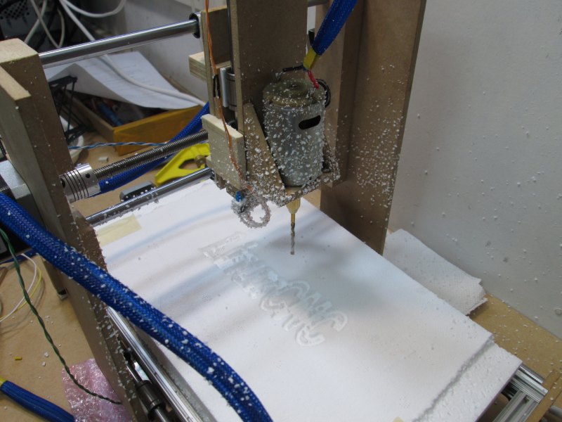
I used a lump of spare polystyrene and the demo file that comes with LinuxCNC. For a cutter I used a 3mm drill bit. After getting the homing about right I set the Z axis touch off and hit run.
The spindle spun up to an insane speed, ear muffs were required. Then it started cutting! It carved "LinuxCNC" out of the foam. Some quick measurements showed the Y axis was twice as high as it should be, but otherwise pretty good. The drill bit made a poor cutter and the chuck on the motor wasn't particularly straight, but it did a reasonable job, and these things can all be fixed :-)

Leave a comment?